Running
Setup
Before running a simulation, there are a few setup stages to perform:
Configure the CPX setup file
Configure the coupling parameters
Configure the input of the mini-apps
Configuring the CPX setup file
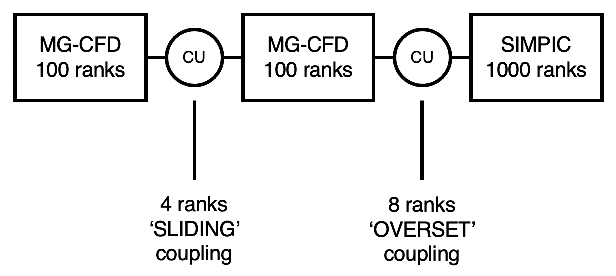
The CPX setup file is called ‘cpx_input.cfg’. It is used to specify the number of cores to allocate to each mini-app and coupler instance, and to define the setup of the simulation. We will take a look at an example to understand the format:
TOTAL 5

MG-CFD 100
MG-CFD 100
SIMPIC 1000

COUPLER 4
TYPE SLIDING
UNIT_1 1
UNIT_2 2

COUPLER 8
TYPE OVERSET
UNIT_1 2
UNIT_2 3
The first line must have the keyword ‘TOTAL’ followed by the total number of instances in the simulation. This value is the sum of the coupler units and mini-app instances. Here, the value is 5, as we are coupling 2 instances of the MG-CFD mini-app, and 1 instance of the SIMPIC mini-app using 2 coupler units.
The next section defines each of the mini-app instances and the number of MPI ranks associated to each instance. Here we have defined two instances of MG-CFD, each with 100 ranks, and 1 instance of SIMPIC with 1000 ranks.
The final section defines the coupler units. The first line specifies the number of ranks assocaited with that coupler unit, the second denotes the coupling type, and the third and fourth lines denote which two mini-app units the coupler units are coupling.
This produces the following configuration:
Configure the coupling parameters
Next to configure are the parameters for the coupling itself. These are set in the ‘coupler_config.h’ header file in the src_op directory, and are used to set how often the coupling takes place and dictate which optimizations are used. It will look similar to the following:
static int coupler_cycles = 5000;
static int mg_conversion_factor = 10;
static int fenics_conversion_factor = 1;
static int search_freq = 6;
static int MUM = 1;
static bool fastsearch = true;
static bool ultrafastsearch = true;
static bool superdebug = false;
static bool debug = false;
static bool hide_search = false;
coupler_cycles defines the number of communication cycles in the coupler units. In each cycle, an ‘interpolation’ routine is performed, where the values from a small slice of the two mini-app instances linked are averaged.
mg_conversion_factor is multiplied by coupler_cycles to calculate the number of MG Cycles (MG-CFD iterations) required to match the production application the mini-app is based off. 10 MG Cycles is equivalent to 1 production code iteration.
fenics_conversion_factor is the same as above but for the FEniCS code. As the FEniCS mini-app uses the same framework as the production application, this value is 1.
search_freq controls how often the search routine is ran in MG-CFD when it is coupled with another MG-CFD unit using the ‘SLIDING’ coupling type. This frequency is set at 6 which mimics the run-time overhead as the production coupled code.
MUM, standing for multi-unit mode, is used to control whether assigning ranks mimics a single coupler unit with multiple ranks or mimics each rank being a coupler unit. For best performance, MUM should be set to 1.
fastsearch controls the algorithm for the search. When it is set to false, a brute force search will be ran. When set to true, a faster tree based search is used.
ultrafastsearch mimics the effect of a cell prediction feature in the production coupler.
superdebug was used in development to disable coupling entirely and allowed mini-apps to run on their own - this is now deprecated
debug controls the amount of output from CPX. Setting the value to true outputs extra information.
hide_search was an experimental feature to overlay the search routine within interpolation routines - this is now deprecated
In general, the only variable worth changing is coupler_cycles, which controls the number of MG-CFD cycles being ran in the simulation.
Configure the input of the mini-apps
The last thing to do is to configure the input of the mini-apps themselves.
MG-CFD
In MG-CFD, input is specified by using the -i flag with the CPX executable at run-time. If a normal input file is provided, all instances of MG-CFD will run that input file. However, it may be beneficial to use different mesh sizes for each instance type. To do so, pass the parameter ‘-i file’ to the cpx executable. This will override the MG-CFD input routine and instead search for a file named ‘mg_files.input’. This file contains a list of MG-CFD input files for each instance of the mini-app, according to the layout specified in the CPX setup (cpx_input.cfg). For example, in simulation specified at the top of this page, the ‘mg_files.input’ may look like this:
input-mgcfd_8m.dat
input-mgcfd_24m.dat
NULL
This would set up a simulation where the first MG-CFD instance has an 8m mesh size, the second MG-CFD instance has a 24m, and the final parameter is left as NULL as the third instance is a SIMPIC instance.
MG-CFD meshes and their assocaited .dat files can be found on the Warwick HPSC downloads page.
SIMPIC
All instances of SIMPIC run from an input file called “simpic_parameters”. This is because as a particle simulation, SIMPIC had been used in place of a combustion chamber in coupled simulations and as such only one instance is necessary in this setup. An example can be found in the SIMPIC directory of the repo. It will look something like this:
-ppc 100 -ncpp 1000 -nt 5 -dtfactor 0.000001 -lhsv 20000 -asz 377
Most of these parameters are the same as those found in the original SIMPIC mini-app. However, there is an additional flag, -asz, which is used to set the size of the SIMPIC interface between instances of other mini-apps in millions of cells. This is because when using SIMPIC to represent a combustion chamber, the size of SIMPIC mesh does not correspond to the size of the mesh that would be used in a typical combustion setup, so we create an artificial interface which we pass to the coupler unit(s).
FEniCS
All instances of FEniCS run from an input file called “Fenics_input”. This is becauase as an FEM simulation, FEniCS is used to simulate the solid regions in coupled simulations and often only one such instance is necessary, there is currently ongoing work to support multiple distinct solid regions. The Fenics input file contains six settings:
Thermal_iterations - the number of inner thermal iterations
Structural_iterations - the number of inner structural iterations
Thermal_outer_its - the number of outer thermal iterations
Structural_outer_its - the number of outer structural iterations
num_vertices - the number of vertices in the mesh
Thermomech_simulation - the flag to control which type of simulation the model uses
The rule of the first four of these is self-explanatory. The variable num_vertices controls the size of the mesh the FEniCS model generates, FEniCS generates a cube mesh with a total number of vertices closest to num_vertices. The final variable, Thermomech_simulation is a flag that controls which simulation the FEniCS model runs. The model is capable of running a full thermo-mech simulation or just a thermal simulation, if Thermomech_simulation is set to 1 the model runs thermo-mech otherwise it runs the simpler thermal simulation.
Running a coupled simulation
With all of these set up, and placed in the directory of the executable (mgcfd_cpx_runtime), your coupled simulation can then be run. This a standard MPI run (or equivalent, depending on your cluster):
mpirun -np 1200 ./mgcfd_cpx_runtime -i file
Remember to ensure the number of ranks specified matches that of the CPX setup file.